Custom Numpad
I really want a split ergonomic keyboard in the vein of an Ergodox, however I don’t want / need a keyboard that costs $CAD 450 and doesn’t even come with the switches I want. I know enough programming and electronics to make my own, but before I dive head-first into a larger project I decided to get started by making a simple numpad to sort out any design issues before going “all in”.
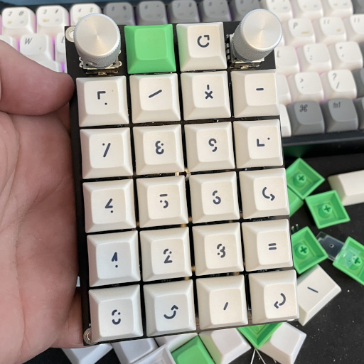
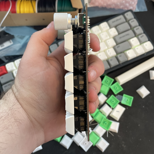
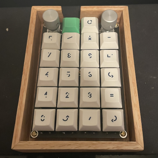
Keyboards are fairly straightforward, just consisting of a matrix of key-switches that are consistently scanned and spit out over USB. As such, I started by laying out a schematic containing a keyboard matrix (with diodes) and connecting that to a Teensy LC. I chose a Teensy LC because it is cheap, easy to use, and way more capable than what I’m using it for. The Teensy LC also has a handy 5V level shifter built in on one of its pins to make connecting to WS2812 LED strips easier. More on that later. Since I don’t want to bother with stabilizers for larger keys for the Enter and + keys, I just replaced these 2u keys with 2 1u keys. For now I’ll just program each of the keys the same, but in the future I could use the extra keys for macros or something.
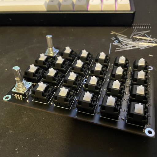
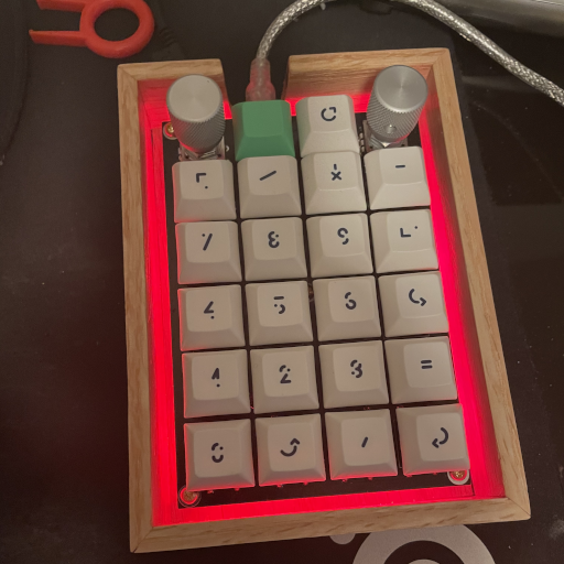
With the macro keys idea in my head I decided to add an additional row to the numpad with some rotary encoders and more keys to fiddle with. As it turns out, the rotation of each encoder can be connected to the matrix in the same manner as two switches. Ultimately this meant I added two additional rows in the schematic, which would result in a single additional physical row with 2 pushbutton encoders & 2 extra key-switches. Finally, I added some WS2812 LEDs and a piezo buzzer for fun.
This may be getting a bit confusing, but the schematic is straightforward enough, see below. I decided to give KiCad a try for this project, and I’m glad I did—it was relatively pleasant to use and ultimately succeeded in a (spoilers) working board!

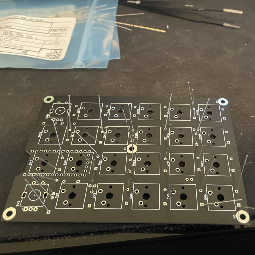
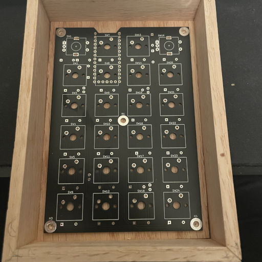
With the schematic out of the way, I moved on to the board layout. This also ended up being fairly straightforward, though I will be making some changes when I go to create my full split keyboard—mostly around spacing. I used the Cherry MX footprints that are included in KiCad for all the key-switches which made laying out the main board quite easy. Then I placed all the diodes next to their key-switches, followed by the encoders, the Teensy, and finally the LEDs & buzzer. Thankfully the key-switches are large enough that laying out extra components was very straightforward. With the layout in place, I continued to route all the nets together; generally preferring the back of the board for horizontal traces and the front for vertical traces. I was able to get away with laying traces for almost the entire board without resorting to any vias, however I need to sneak a few in for the LEDs.

I made all of the traces 0.5mm where possible, shrinking down only where necessary, and left double the minimum spacing between traces & holes according to JLCPCB’s capabilities. With the traces completed, I flooded the copper with ground fills to get the final layout:


This was my first time ordering from JLCPCB and I would definitely do so again. The whole process (with the exception of FedEx losing my package in the ether until it magically appeared a month and a half after the expected delivery, but that’s not JLCPCB’s fault) was smooth & inexpensive. The components (with the exception of the key-switches) were ordered from Digikey, and the key-switches (Cherry MX clears—the ultimate keys in my opinion) came from NovelKeys_.
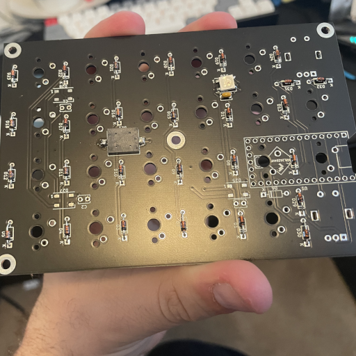
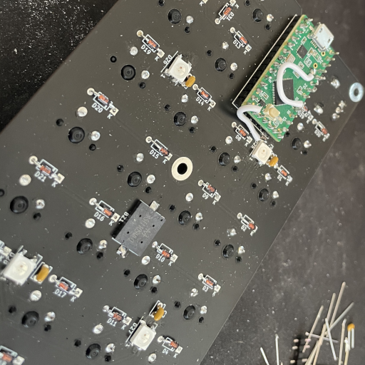
Once everything was in hand, it was time for assembly, starting with a test of the surface mount LEDs and the diodes:
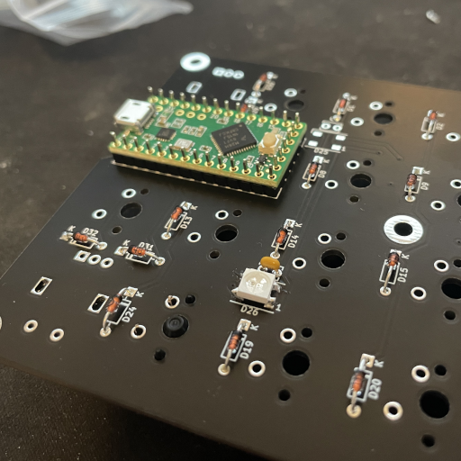
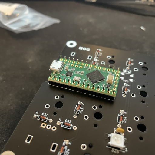
After those were in place, I decided to place the Teensy on the board. This ended up being a bit tricky because I didn’t leave enough space between the end pins and the switch that they overlapped. Ultimately I solved it by only soldering the through-hole headers almost flush with the board. There’s no real reason to not move the Teensy down however, and that’s something I’ll definitely be doing in future designs in order to tighten things up.
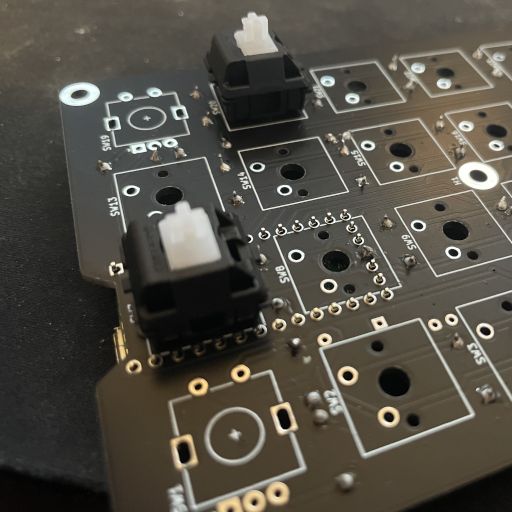
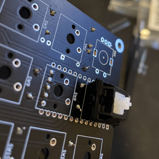
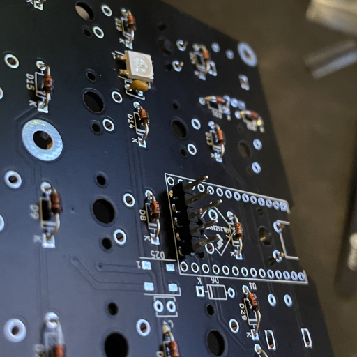
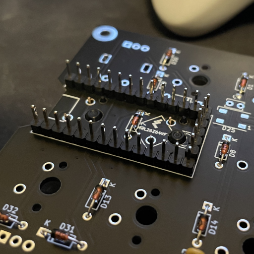
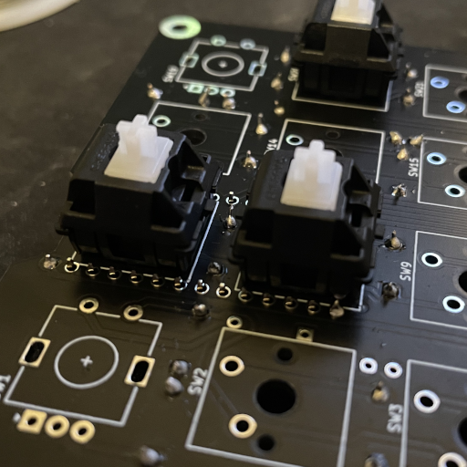
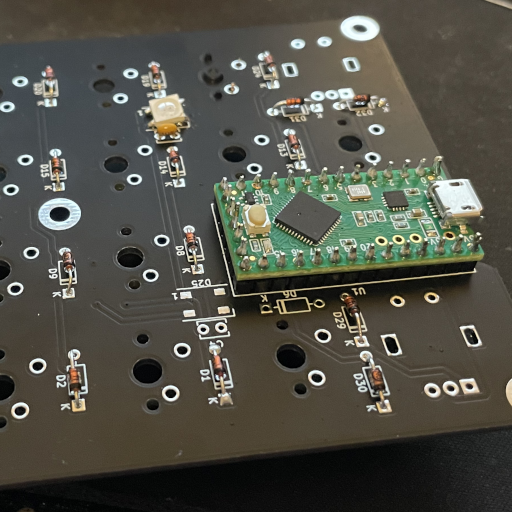
With that in place, I could finally move on to soldering the remaining components on:
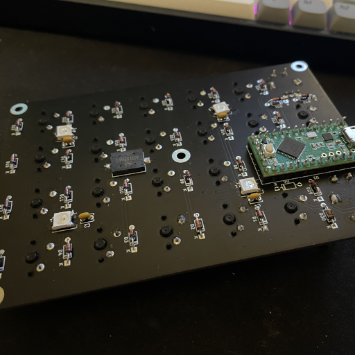
At this point I started testing the board with basic firmware—detecting key presses, playing bleeps and bloops on the buzzer, and lighting up the LEDs. Lighting up the LEDs didn’t work right away; after a brief investigation I realized that although the Teensy LC breaks out a 5V LED control line on pin 17, the normal pin 17 on the side isn’t actually connected this way and the actual pin is on the end of the board. Further, the library I wanted to use (WS2812Serial) required using pin 24—one of the pins in the middle of the board that I had left completely unconnected! To fix these issues, I cut the trace from the Teensy pin 17 to the LEDs then soldered a jumper from pin 24 to pin 17, and another jumper from the end “pin 17” to the LEDs. Finally, after these mods, I was able to get the LEDs to work. Definitely something to keep in mind for future boards.
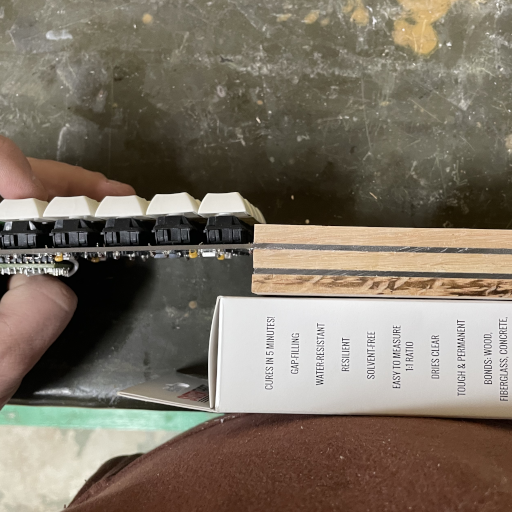
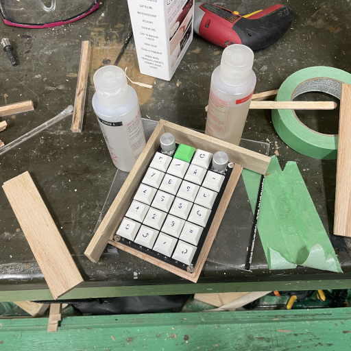
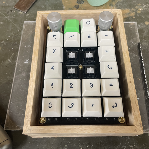
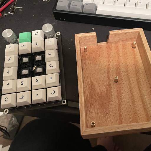
With the electronics sorted, I dug out some old keycaps I wasn’t using and got to work creating a simple case for it.
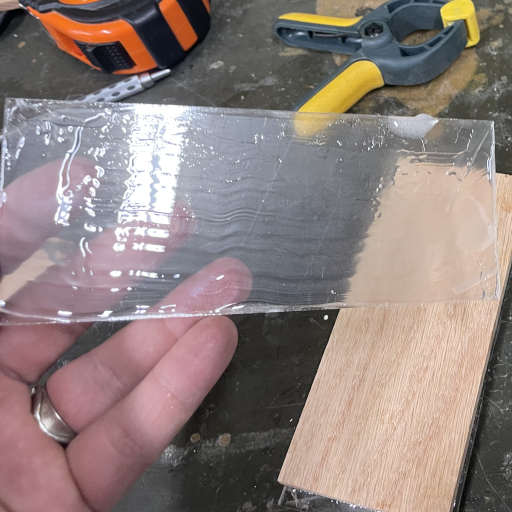
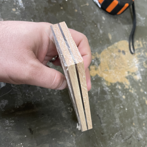
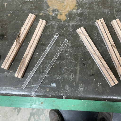
Since I had a few LEDs on the bottom of the board, I decided to include some clear plexiglass in the case to let the LEDs shine through. I figured I could stack a few layers of ¼” wood with a few layers of 0.080” plexiglass and then cut out thin strips to build walls out of. This started out fairly straightforward:
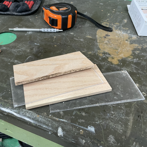
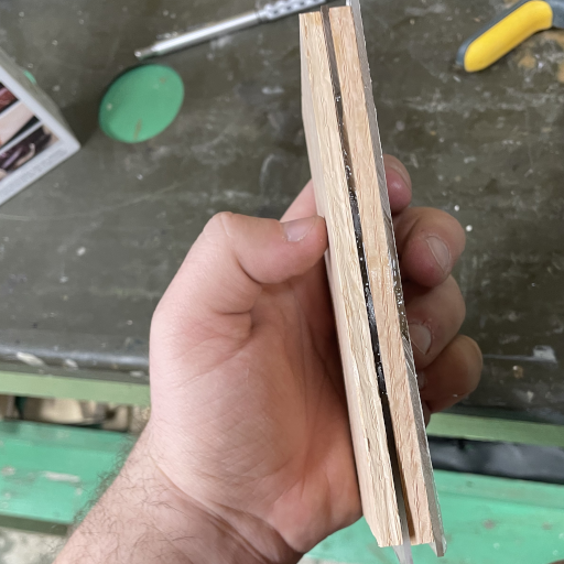
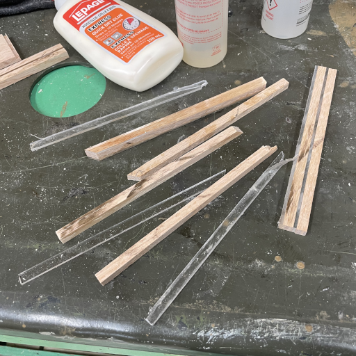
Unfortunately, this design quickly unravelled as soon as I cut my block into thin strips for walls—the epoxy I used to bind the layers did not keep them together at all. A couple of the pieces exploded on the table saw, and the ones that came out fine crumbled under the slightest pressure. I’m not sure what exactly went wrong; though I suspect either I used the wrong epoxy for this job or the ratio was wildly off. In any event, since this was supposed to be a quick job, I decided not to fart around with it and just put together a more straightforward wooden box.
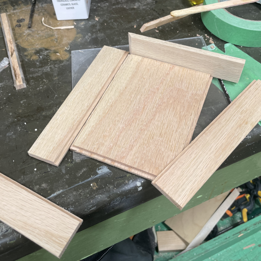
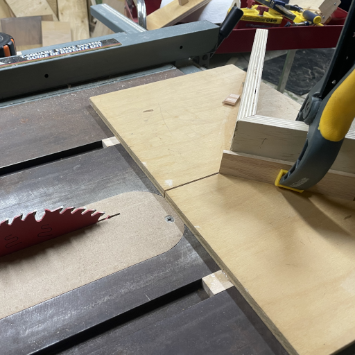
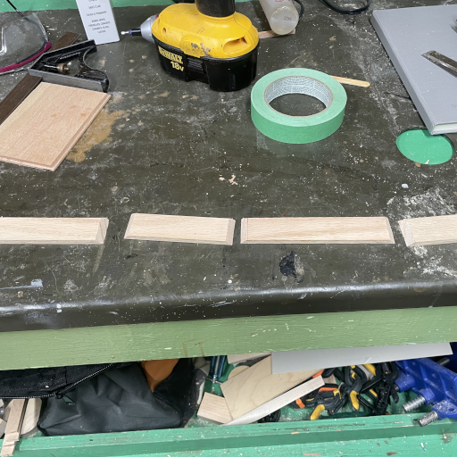
I built the box using half-rabbets all along the base and a mitre joint on all the vertical edges. For such a small box that won’t be put under any stress whatsoever, the joints don’t really matter other than for aesthetics. I first rabbetted all of the pieces and then cut each to length to fit using a mitre sled jig. This was my first time using this jig and it went rather well.
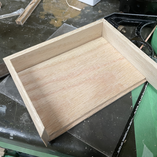
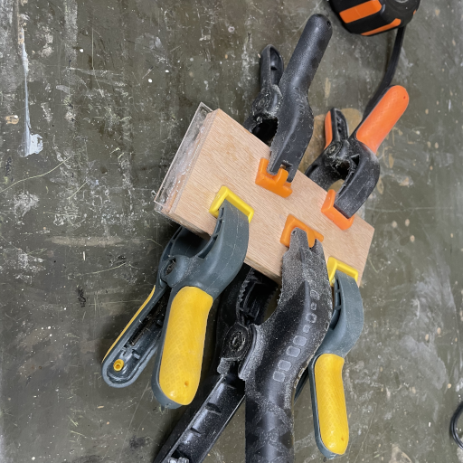
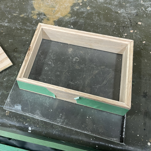
Once the pieces were cut I used tape to help me glue together all the edges, then went way overboard clamping it all together since it was time to head in for the day anyway.
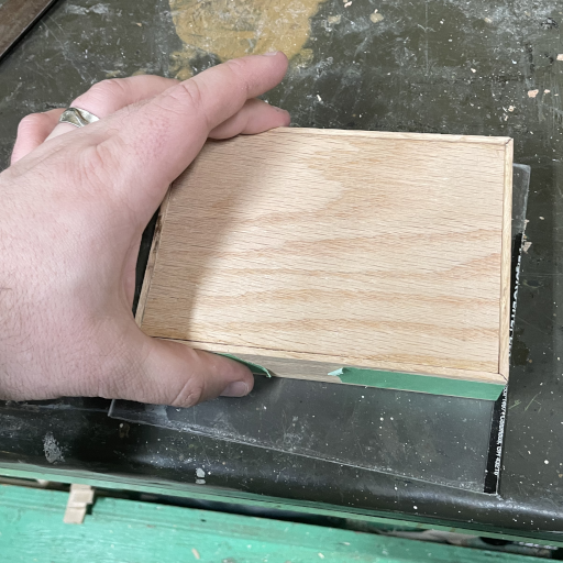
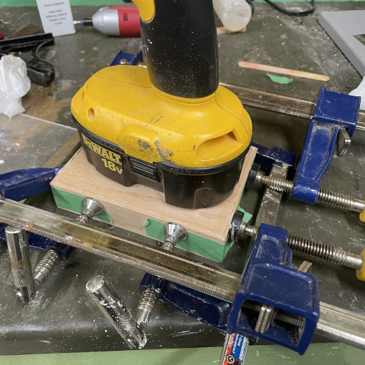
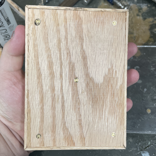
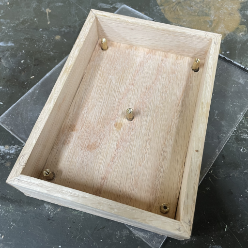
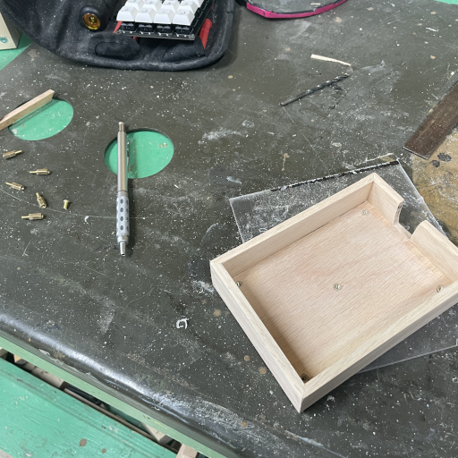
The next day, I removed the clamps, marked where to drill holes for the support ports, and drilled them out. One of the holes ended up quite a bit off track; the drill bit must have wandered quite a bit without me noticing. Thankfully it was easy enough to correct by enlarging the hole. It would have been nice to not have to drill holes all the way through the bottom, but the brass inserts I had were more or less the same depth as the ¼” red oak board I used as a base. I epoxied threaded M3 brass inserts into the holes with the M3 posts attached to the board to ensure that everything would line up nicely.
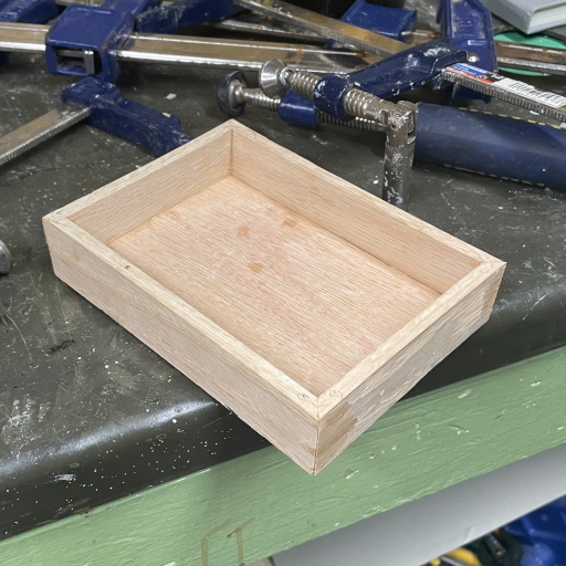
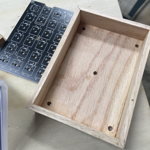
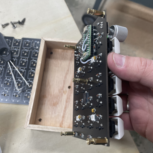
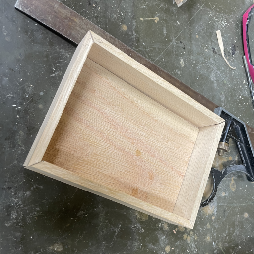
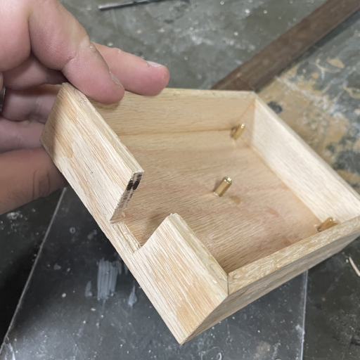
At this point, I remembered that I had to plug a USB cable through the case somehow. So, I cut out a janky slot for the cable to pass through and then proceeded to sand the whole thing down with 120-grit and then 220-grit sandpaper. Once it was nice and smooth, I cleaned the box with a bit of mineral spirits and then finished with some Tried and True Original Wood Finish, letting it dry overnight.
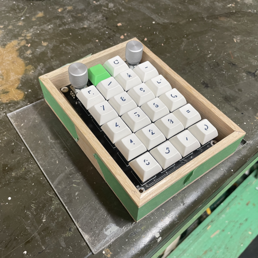
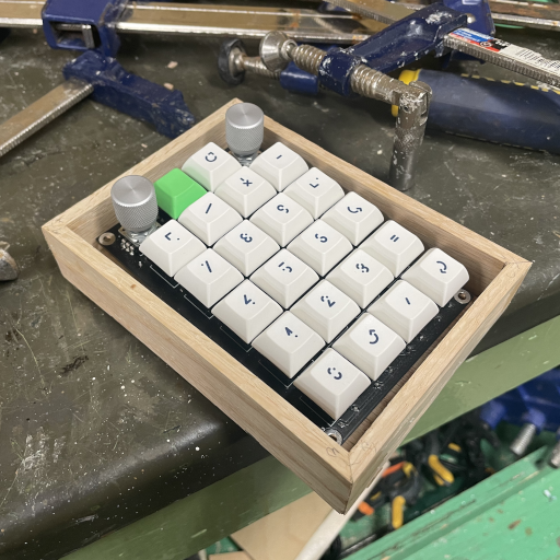
Finally, it was time to place the board into the case and finish the firmware. The firmware didn’t take long to get an MVP up and running. It’s at a state where I don’t quite know what else to add to it, so its probably time to clean it up and simplify it. The firmware source is available at https://github.com/hamaluik/numpad-firmware.
All in all, this was a really satisfying project that scratched several itches. From designing the electronics, to assembling it, programming the firmware, and putting together a little box for it, I got to stretch my legs a bit while learning several things along the way. If you’re at all curious about electronics or are in love with mechanical keyboards, I suggest you do a project like this—it’s easier than you might think, and you get a very rewarding and usable tool at the end!